


12 - 34
MELSEC-
A
12 CONTROL AUXILIARY FUNCTIONS
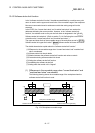
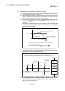
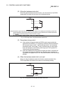
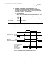
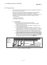
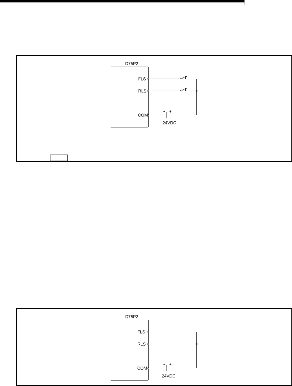
(2) Wiring the hardware stroke limit
When using the hardware stroke limit function, wire the terminals of the D75P2
upper/lower limit stroke limit as shown in the following drawing.
Note) Connect the upper and lower limit switches to the directions of increasing and decreasing current feed
values respectively. When these switches are connected in wrong directions, the hardware stroke limit
function does not operate properly and the motor does not stop.
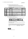
For "
Pr.6
Rotation direction setting", refer to "5.2.1 Basic parameter 1".
Fig. 12.20 Wiring when using the hardware stroke limit
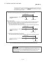
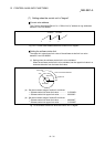
(3) Precautions during control
(a) If the machine is stopped outside the D75P2 control range (outside the
upper/lower limit switches), or if stopped by hardware stroke limit detection,
the "zero point return control", "main positioning control", and "advanced
positioning control" cannot start. To carry out these types of control again,
return the workpiece to the D75P2 control range by a "JOG operation" or
"manual pulse generator operation".
(b) If the circuit between the RLS (lower limit signal) and COM, or between the
FLS (upper limit signal) and COM is open (including when not wired), the
upper/lower limit signals will turn OFF, and control with the D75P2 will not be
possible.
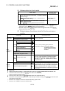
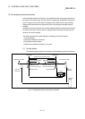
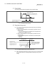
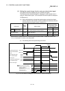
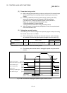
(4) When the hardware stroke limit is not used
When not using the hardware stroke limit function, wire the terminals of the
D75P2 upper/lower limit stroke limit as shown in the following drawing.
Fig. 12.21 Wiring when not using the hardware stroke limit