


4 - 2
MELSEC-
A
4 INSTALLATION, WIRING AND MAINTENANCE OF THE PRODUCT
4.1 Outline of installation, wiring and maintenance
4.1.1 Installation, wiring and maintenance procedures
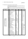
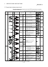
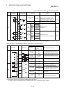
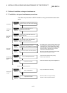
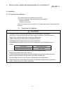
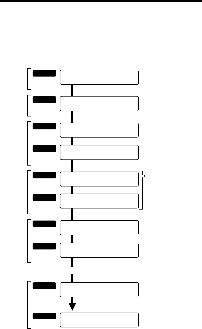
The outline and procedures for D75P2 installation, wiring and maintenance are shown
below.
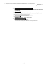
STEP 7
STEP 8
STEP 9
STEP 10
Refer to
section 4.8
Refer to
section 4.8
Refer to
section 4.7
Confirmin
g
the
installation and
w
irin
g
Carry out the single module test
Confirm that the D75P2 functions properly
with the single module test.
Servicing the
module
Confirm the connection
Check the connection using the GX Configurator-AP.
Operation of the positioning system.
Carry out maintenance
Carry out maintenance as necessary.
Dispose of the D75P2
When the D75P2 is no longer necessary,
dispose of it with the specified methods.
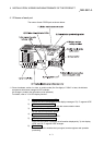
STEP 5
STEP 6
Refer to
section 4.5
Refer to
section 4.5
Wiring the
drive unit
Wire the external device connection
connector pins, and assemble the connector.
The cables used to connect the D75P2 with the drive
unit, the D75P2 with the machine system input (each
input/output signal), and the D75P2 with the manual
pulse generator are manufactured by soldering each
signal wire onto the "external device connection
connector" enclosed with the D75P2.
Connect the cable to the module (D75P2)
Wire and connect the manufactured cable to D75P2
after reading the precautions for wiring.
*
*
*
*
*
STEP 1
STEP 2
Refer to
section 4.2
Refer to
section 4.1
Preparation
Understand the "Handling precautions" and
"Names of each part" of the module (D75P2)
Installing the
module
Install the module (D75P2) on the
DIN rail/enclosure surface
STEP 3
STEP 4
Refer to
section 4.3
Connection and
settin
g
as
CC-Link
Wire the CC-Link dedicated cables to the
module (D75P2).
Refer to
section 4.4
Set the station number and transmission
speed of the module (D75P2).