


4 - 8
MELSEC-
A
4 INSTALLATION, WIRING AND MAINTENANCE OF THE PRODUCT
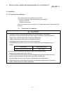
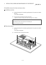
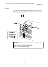
(2) Precautions for installation into control box
• Control box hole
The diameter of a control box hole should be 10cm or less. If the hole is more
than 10cm, radio waves may leak. Also, eliminate gaps between the control
box door and module as far as possible since radio waves will leak through
them.
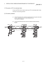
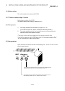
Radio wave leakage can be suppressed by applying the following EMI gasket
directly to the painted surface to stop up gaps.
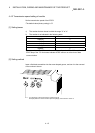
Maker name Series name
Kitagawa Kogyo Co., Ltd. UC Series
Japan Zipper Tubing Co., Ltd. 71TS Series
Seiwa Electric Mfg Co., Ltd.
E02S
A
Tests have been conducted by us in a control box having the damping
characteristics of maximum 37dB and average 30dB (30 to 300MHz, 3m
measurement).
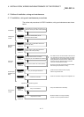
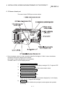
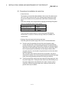
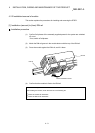
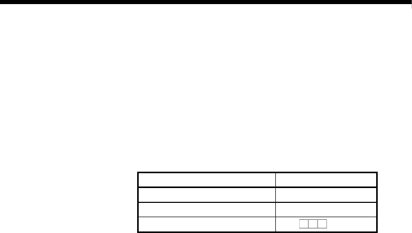
• Routing of the power supply wires and ground wires
Route the ground and power supply wires of the PLC as described below.
(a) Provide a point for grounding the control box near the power supply
module, and earth the LG terminal (line ground) and FG terminal (frame
ground) of the power supply module with the thickest and shortest possible
(about 30cm or less wire length) ground wires (wires for grounding). Since
the LG terminal and FG terminal serve to drive away the noise, which
occurred in the PLC, into the earth, the ground wires must have the lowest
possible impedance.
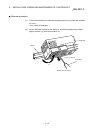
Also, the ground wires must be wired as short as possible. The ground
wires serve to release noise. Since the ground wires themselves have large
noise, short wiring prevents themselves from acting as antennas.
(b) Twist the ground wires, which have been drawn from the ground point, with
the power supply wires. Twisting the wires allows more noise flowing out of
the power supply wires to be released into the earth. However, when a
noise filter is fitted to the power supply wires, twisting of them with the
ground wires may not needed.