12 - 31
MELSEC-
A
12 CONTROL AUXILIARY FUNCTIONS
(5) Setting the software stroke limit function
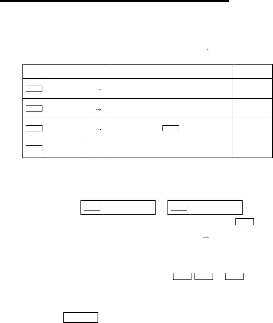
To use the "software stroke limit function", set the required values in the
parameters shown in the following table, and write them to the D75P2.
The set details are validated at the rising edge (OFF
ON) of the remote station
READY signal [RX(n+7)B].
Setting item
Setting
value
Setting details
Factory-set
initial value
Pr.13
Software stroke
limit upper limit
value
Set the upper limit value of the moveable range. 2147483647
Pr.14
Software stroke
limit lower limit
value
Set the lower limit value of the moveable range. –2147483648
Pr.15
Software stroke
limit selection
Set whether to use the "Current feed value (RWrn+0
to 1, RWrn+8 to 9)" or "
Md.30 Machine feed value"
as the "current value".
0: Current feed
value
Pr.16
Software stroke
limit valid/invalid
setting
1:Valid
Set whether the software stroke limit is validated or
invalidated during manual control (JOG operation,
manual pulse generator operation).
0: Invalid
* Refer to section "5.2 List of parameters" for setting details.
(6) Invalidating the software stroke limit
To invalidate the software stroke limit, set the following parameters as shown,
and write them to the D75P2. (Set the value within the range.)
Pr.13
Software stroke limit
upper limit value
=
Pr.14
Software stroke limit
lower limit value
(For manual operation, set "0: software stroke limit invalid" in the "
Pr.16
Software stroke limit valid/invalid setting".)
The set details are validated at the rising edge (OFF
ON) of the remote station
READY signal [RX(n+7)B].
When the unit is "degree", the software stroke limit checks are not made during
speed control (including speed control of speed/position changeover control) and
during manual control, regardless of the
Pr.13 , Pr.14 and Pr.16 setting
values.
REMARK
Parameters are set for each axis.


