


3 - 10
MELSEC-
A
3 SPECIFICATIONS AND FUNCTIONS
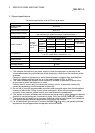
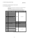
3.3.3 D75P2 auxiliary functions and common functions
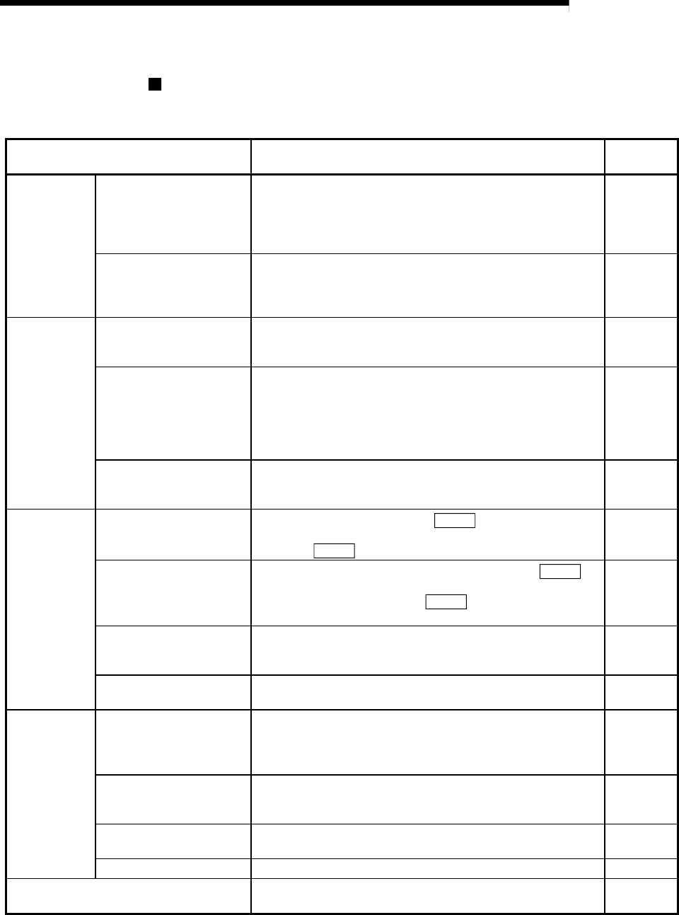
Auxiliary functions
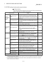
The functions that assist positioning control using the D75P2 are described below.
(Refer to "SECTION 2" for details on each function.
Auxiliary function Details
Reference
section
Functions
characteristic
to machine
zero point
return
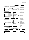
Zero point return retry
function
This function retries the machine zero point return with the
upper/lower limit switches during machine zero point return.
This allows machine zero point return to be carried out even if
the axis is not returned to before the near-point dog with JOG
operation, etc.
12.2.1
Zero point shift function
After returning to the machine zero point, this function
compensates the position by the designated distance from the
machine zero point position and sets that position as the zero
point address.
12.2.2
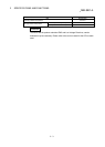
Functions that
compensate
control
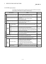
Backlash compensation
function
This function compensates the mechanical backlash. Feed
pulses equivalent to the set backlash amount are output each
time the movement direction changes.
12.3.1
Electronic gear function
By setting the movement amount per pulse, this function can
freely change the machine movement amount per commanded
pulse.
When the movement amount per pulse is set, a flexible
positioning system that matches the machine system can be
structured.
12.3.2
Near pass mode function
This function suppresses the machine vibration when the
speed changes during continuous path control in the
interpolation control.
12.3.3
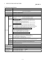
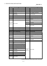
Functions that
limit control
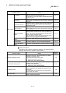
Speed limit function
If the command speed exceeds "
Pr.7
Speed limit value"
during control, this function limits the commanded speed to
within the "
Pr.7
Speed limit value" setting range.
12.4.1
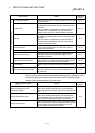
Torque limit function *
1
If the torque generated by the servomotor exceeds "
Pr.18
Torque limit setting value" during control, this function limits the
generated torque to within the "
Pr.18
Torque limit setting
value" setting range.
12.4.2
Software stroke limit
function
If a command outside of the upper/lower limit stroke limit
setting range, set in the parameters, is issued, this function will
not execute positioning for that command.
12.4.3
Hardware stroke limit
function
This function carries out deceleration stop with the limit switch
connected to the D75P2 external device connection connector.
12.4.4
Functions that
change control
details
Speed change function
This function changes the speed during positioning operation.
This function sets a new speed to "New speed value
(RWwm+4 to 5, RWwm+12 to 13)" and changes the speed at
the speed change request (RY(n+2)7, RY(n+4)7).
12.5.1
Override function
This function varies the speed during positioning operation at
the ratio of 1 to 300%. "Positioning operation speed override
(RWwm+1, RWwm+9)" is used to execute this function.
12.5.2
Acceleration/deceleration
time change function
This function changes the acceleration/deceleration time during
speed change.
12.5.3
Torque change function This function changes the "torque limit value" during control. 12.5.4
Absolute position restoration function*
2
This function restores the absolute position of the specified
axis.
12.6
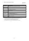
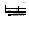
*
1
To carry out "torque limit", the "D/A conversion module" and a "drive unit capable of the torque limit command with
an analog voltage" must be prepared.
*
2
The "drive unit that can configure an absolute position detection system (MR-H, MR-J2, MR-J2S)" is required to
perform "absolute position restoration".