


6 - 18
MELSEC-
A
6 SEQUENCE PROGRAM USED FOR POSITIONING CONTROL
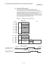
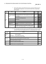
(2) About control data
When transmitting data using the transient transmission, the control data must be
added to the transmission data before transmitting.
When receiving data, the control data will be added to the head of the reception
data.
The following examples are explained for the control data.
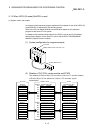
Transmission buffer address (200H worth) :
M
1000H to 11FFH
Reception buffer address (200H worth) :
M
1200H to 13FFH
POINT
Refer to the following manuals for details on the control data when using the
dedicated commands (RIWT/RIRD).
When using QnACPU : QnACPU Programming Manual (Special Function
Module)
When using QCPU (Q mode) : QJ61BT11N User's Manual
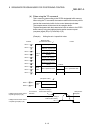
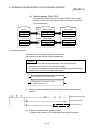
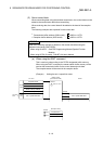
(a) When using the RIWT command
This is used only when writing to the D75P2-designated buffer memory.
When using the RIWT command, the master station buffer memory will be
used as the transmission buffer for the control data and write data.
The complete status will be stored in the reception buffer.
(Example) Writing the axis 1 speed limit value
D75P2
6
H
7
H
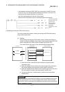
PLC CPU
Master module
(Transmission buffer)
Address
1000
H
to 11FF
H
M
Address
One word
each
Write
data
Axis 1 speed limit value Axis 1 speed limit value
(Reception buffer)
Complete status
Station No., request code
Address
1200
H
M
1201
H
M
Control
data
Complete status
Station No.
Access code, attribute
Buffer memory address
Number of write points (word)