


DEFINITY ECS Release 8.2 Maintenance for R8.2csi
555-233-119 Issue 1
April 2000
Maintenance for csi systems
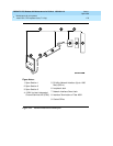
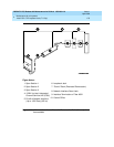
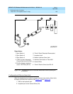
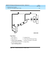
1-74Install DS1 CPE Loopback Jack (T1 Only)
1
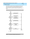
4. Enter
test ds1-loop <location> cpe-loopback-jack
. This turns on simplex
power to the loopback jack and waits about 20 seconds for any active
DS1 facility alarms to clear. A “PASS” or “FAIL” displays on the terminal.
This is the first of the 2 results. A “FAIL” indicates a fault is present in the
wiring between the ICSU and the loopback jack. The loopback jack may
also be faulty. A “PASS” only indicates that the loopback jack looped
successfully, not that the test data contains no errors. If a “PASS” is
obtained, continue with the following steps.
NOTE:
The loss of signal (LOS) alarm (demand test #138) is not processed
during this test while the 3-in-24 pattern is active.
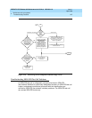
5. Enter
clear meas ds1 loop <location>
to clear the bit error count.
6. Enter
clear meas ds1 log <location>
to clear the performance
measurement counts.
7. Enter
clear meas ds1 esf <location>
to clear the ESF error count.
8. Enter
list meas ds1 sum <location>
to display the bit error count. Refer
to
Table 1-7
for troubleshooting information.
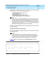
Table 1-7. DS1 Span Troubleshooting
Displayed
Field Function Indication
Test: cpe-
loopback-jack
Pattern 3-in-24 The loopback jack test is active.
Synchronized Y or N If “y” displays, the DS1 circuit pack has
synchronized to the looped 3-in-24 pattern and is
accumulating a count of the bit errors detected in
the pattern until the test has ended. If
n displays,
retry the test 5 times by ending the test per Step
11 and re-starting the test per Step 4. If the circuit
pack never synchronizes, substantial bit errors in
the 3-in-24 pattern are likely. This could be
intermittent connections or a broken wire in a
receive or transmit pair in the CPE wiring.
Continued on next page