


DEFINITY ECS Release 8.2 Maintenance for R8.2csi
555-233-119 Issue 1
April 2000
Maintenance Commands
2-34change system-parameters maintenance
2
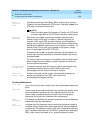
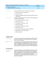
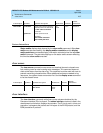
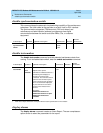
Output (Page Three)
The following example shows the output from
page 3
of the
change
system-parameters maintenance
command.
Field descriptions (Page Three)
Modem Connection
On page 3 of the example forms, 11 fields disappear when the
Modem
Connection?
field is set to
internal
. In this example the
Modem Connection
field is set to
external
, revealing the 11 fields.
The first 2 fields on page 3 establish the data format for transmitting serial data
from the switch to the modem. The two valid combinations for these 2 fields are:
■ Data Bits = 8, Parity = None
■ Data Bits = 7, Parity = (odd, even, mark, or space)
Modem Connection
Valid entries are
internal
(default) or
external
.
Modem Name
This field is 20 characters long and will permit alpha-numeric
characters to provide a unique qualifier for a given modem. ( )
RTS/CTS Enabled
This field will inform the modem that communication with the data
source UART will be driven with RTS/CTS flow control. This field is
6 characters long and is case in-sensitive. (\Q3)
change system-parameters maintenance Page 3 of 3
MAINTENANCE-RELATED SYSTEM PARAMETERS
Modem Connection: external
Data Bits: 8
Parity: none
Modem Name: _______
RTS/CTS Enabled: \Q3 Auto Answer Ring Count (rings): S0=10
Asynchronous Data Mode: &M0&Q0 Dial Type: T
DTE Auto-Data Speed: ______ Adjustable Make/Break Ratio:
Disable Data Compression: ______ Dial Command: D
Enable Error Control: ______ No Answer Time-out: S7=255
Misc. Init. Param: ______________
Help/Error Message Line