


DEFINITY ECS Release 8.2 Maintenance for R8.2csi
555-233-119 Issue 1
April 2000
Maintenance Objects
3-1023TBRI-BD (TN2185 ISDN Trunk-Side BRI)
3
TBRI-BD (TN2185
ISDN Trunk-Side BRI)
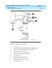
The TN2185 circuit pack contains eight, 4-wire ports that interface to the network
at the ISDN S/T reference point over two 64 Kb/s channels (B1 and B2) and over
a 16Kb/s signaling (D) channel. The B1 and B2 channels can be simultaneously
circuit switched, or individually packet switched. Only one channel per trunk can
be packet switched due to Packet Processing Element (PPE) limitations. The D
channel is either circuit switched or packet switched. Packet switching uses the
PPE to combine all D channels into a single physical channel, which is then
routed via the concentration highway to the Network Control Element (NCE) and
then to the TDM bus. The circuit-switched connections have a Mu-law or A-law
option for voice and operate as 64Kb/s clear data channels. The
packet-switched channels support the LAPD protocol and conform with the
CCITT Q.920 Recommendations for D-channel signaling.
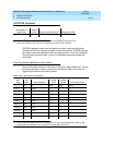
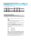
LEDs
The three LEDs on the circuit pack’s faceplate indicate board status. When
illuminated, the red LED indicates a board failure or a major or minor on-board
alarm, the green LED indicates that testing is in progress, and the amber LED
indicates that the board is in use.
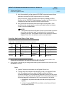
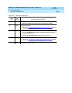
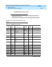
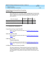
MO Name (in
Alarm Log) Alarm Level Initial Command to Run
1
1. Where P is the port network number (1), C is the carrier designation (A, B, or C), and SS is the
the carrier slot address where the circuit pack is located (1, 2, and so forth).
Full Name of MO
TBRI-BD MINOR test board PCSS l r# TBRI-BD