


DEFINITY ECS Release 8.2 Maintenance for R8.2csi
555-233-119 Issue 1
April 2000
Maintenance Objects
3-143ATM-EI (Expansion Interface Circuit Pack)
3
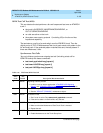
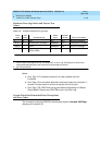
LEDs
The ATM Interface circuit pack has three LEDs:
■ red indicates some alarm condition
■ green indicates maintenance testing in progress
■ yellow provides useful visual information regarding the operating mode of
the ATM-EI and possible error conditions.
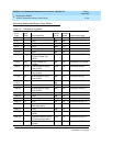
The possible LED states are in Table 3-61
.
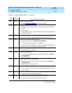
Table 3-61. ATMInterface LED codes
LED LED status Condition
Red Steady on Board is not healthy
Never on Normal conditions
Red and
Green
Red LED solid on
Green LED 200 ms on; 200 ms off
Board is in the processes of booting
Green Steady on
1
1. The green LED flashes between tests.
Maintenance is running tests on the board
100 ms on - 100 ms off No links to the board
Yellow 100 ms on -100 ms off Fiber Loss of Signal (LOS), LOF, MS_RDI,
MS_AIS, LCD, HP_RDI, HP_AIS, LOP, PSC
(See Table 3-65
)
Yellow 500 ms on; 500 ms off Signal to the ATM switch is down
Yellow 2 s on; 0.2 s off ATM-EI is Expansion Archangel (EAA)
Yellow Steady on ATM-EI active (PPN)
Yellow Never on ATM-EI standby
Continued on next page