


DEFINITY ECS Release 8.2 Maintenance for R8.2csi
555-233-119 Issue 1
April 2000
Maintenance Objects
3-1066TDM-BUS (TDM Bus)
3
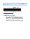
Procedure 3
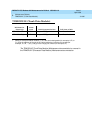
Procedure 3attempts to isolate the failure to a particular set of carriers, and then
checks only the circuit packs in those carriers. This procedure involves
terminating the TDM Bus so that certain carriers are disconnected from the TDM
Bus. This is done by moving the TDM Bus terminators (AHF1) on the carrier
backplane. To terminate a TDM Bus at the end of a particular carrier, the TDM
Bus cable that connects the carrier to the next carrier should be unplugged and
replaced with the TDM Bus terminator. The TDM Bus terminators can be taken
from one carrier to the other. To get to the TDM Bus cables, remove the back
cover of the cabinet. When the length of the TDM Bus is modified via this
procedure, the circuit packs that are essential to system operation and TDM Bus
maintenance (for example, Network Control circuit pack, Tone-Clock circuit pack,
Tone Detector circuit pack) must still be connected to the new
shortened
TDM
Bus.
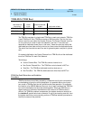
For the Processor Port Network (PPN)
1. Terminate the TDM Bus so that it extends within the control carrier.
2. Run the
test tdm
system technician command. If any of the TDM Bus tests
fail, perform Procedure 2 and/or Procedure 3 for only the circuit packs in
those carriers connected to the
shortened
TDM Bus. Procedure 2 is
performed for port circuit packs (purple slots) and Procedure 3 for control
carrier circuit packs.
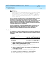
3. If none of the TDM Bus tests fail, extend the TDM Bus to another carrier
and repeat this procedure. When a carrier is added that causes some of
the TDM Bus tests to fail, perform Procedure 2 and/or Procedure 3 for only
the circuit packs in that carrier.
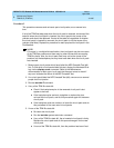
Restarting Nonfunctioning Port Circuit Packs
A defective TDM Bus Control Channel or system timing reference on one of the
networks can result in port circuit packs (that is non-control carrier circuit packs)
on this defective network entering the reset state. When this situation occurs, the
circuit pack stops functioning and its red LED lights. The system does not detect
the presence of a circuit pack when the circuit pack is in the reset state. Hence,
executing the
list config board PCSS
command indicates that the circuit pack is
not present.
If a circuit pack enters the reset state when the control channel is on TDM Bus PT
(where network P contains the circuit pack), this circuit pack stops functioning
until it receives a restart message when the control channel is on the same TDM
Bus PT or when this circuit pack is powered up again.