


DEFINITY ECS Release 8.2 Maintenance for R8.2csi
555-233-119 Issue 1
April 2000
Maintenance for csi systems
1-76Install DS1 CPE Loopback Jack (T1 Only)
1
b. The DS1 cannot frame on the incoming span’s signal after the
loopback jack is powered down. This means that there is
something wrong with the receive signal into the loopback jack from
the “dumb” block or the Smart Jack. If the service provider
successfully looped and tested the span, up to the Smart Jack, this
condition isolates the problem to the wiring between the loopback
jack and the Smart Jack. Refer to ‘‘Loopback Jack Fault Isolation
Procedures’’ for information on how to proceed in this case. The
test cannot be successfully terminated until a good signal is
received. To properly terminate the test before a good receive
signal is available, enter
reset board <location>
.
12. Restore the
TX LBO
field to the original value recorded in Step 2.
13. Release the DS1 circuit pack using the
release board PCSSpp
command.
14. Leave the loopback jack connected to the DS1 span.
Loopback Jack Fault Isolation Procedures
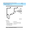
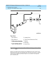
This section describes the possible DS1 configurations in which the loopback
jack may be used. These configurations are: when the DS1 provider includes a
Smart Jack, when no Smart Jack is provided at all, and when sites use fiber
multiplexers.
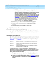
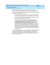
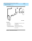
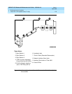
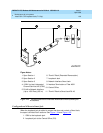
Configurations Using a Smart Jack
The addition of the loopback jack and the presence of a Smart Jack divides the
DS1 span into 3 separate sections for fault isolation. These sections are shown in
Figure 1-21
through
Figure 1-23
for the different span configurations. They are:
A problem can exist in 1 or more of the 3 sections. The field technician is
responsible for finding and correcting problems in the first 2 sections. The DS1
service provider is responsible for finding and correcting problems in the third
section. Testing is divided into 3 steps.
■ Test customer premises wiring (section 1 in the following 3 figures) from
the ICSU to the loopback jack as described in “DS1 Span Test.”
■ Test the CO-to-network interface wiring (section 3 in
Figure 1-21
) using the
Smart Jack loopback (CO responsibility). Coordinate this test with the DS1
provider.
Section 1: Between the 120A2 (or later) ICSU and the loopback jack.
Section 2: Between the loopback jack and the Smart Jack (network
interface point).
Section 3: From the Smart Jack to the CO. It is necessary to contact
the DS1 provider to run this test.