


DEFINITY ECS Release 8.2 Maintenance for R8.2csi
555-233-119 Issue 1
April 2000
Maintenance for csi systems
1-84LED Interpretation
1
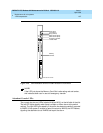
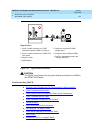
Configurations Using Fiber Multiplexers
Use the loopback jack when customer premises DS1 wiring connects to an
on-site fiber multiplexer (MUX) and allows wiring to the network interface point on
the MUX to be remotely tested. This requires that ICSUs be used on DS1 wiring
to the MUX.
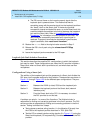
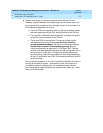
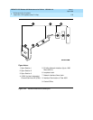
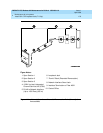
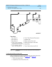
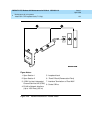
Fiber MUXes can take the place of Interface termination feeds as shown in
Figure 1-21
, Figure 1-22, Figure 1-23, and Figure 1-24. Test these spans using
the same procedures as metallic spans. Note the following points:
1. Fiber MUXes may have loopback capabilities that can be activated by the
service provider from the CO end. These may loop the signal back to the
CO or back to the DS1 board. If the MUX provides the equivalent of a line
loopback on the “problem” DS1 facility, this may be activated following a
successful loopback jack test and used to isolate problems to the wiring
between the loopback jack and the MUX.
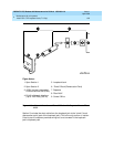
2. Be aware that there are installations that use repeatered metallic lines
between the MUX and the “dumb” block. Theses lines require DC power
for the repeaters and this DC power is present at the “dumb” block
interface to the CPE equipment.
A loopback jack is required in this
configuration to properly isolate and terminate the DC power
.
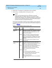
To check for the presence of DC, make the following 4 measurements at the
network interface jack:
1. From Transmit Tip (T, Pin 5) to Receive Tip (T1, Pin 2)
2. From Transmit Ring (R, Pin 4) to Receive Ring (R1, Pin 4)
3. From Transmit Tip (T, Pin 5) to Transmit Ring (R, Pin 4)
4. From Receive Tip (T1, Pin 2) to Receive Ring (R1, Pin 4)
All measurements should read 0 (zero) volts DC. For pin numbers and pin
designations, refer to
Integrated Channel Service Unit (ICSU) Installation and
Operation
, 555-230-193.
LED Interpretation
The lighting and unlighting of LEDs indicates to the system user the status of
various maintenance components in the system. LEDS are located on the
attendant console, on all circuit packs in the switch cabinets and, optionally, on
customer-designated voice terminals. The following LEDS are included in the
system:
■ ‘‘TN798 Processor Circuit Pack LEDs’’
■ ‘‘Attendant Console LEDs’’