


DEFINITY ECS Release 8.2 Maintenance for R8.2csi
555-233-119 Issue 1
April 2000
Maintenance for csi systems
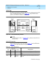
1-103ATM Tips
1
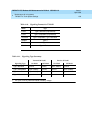
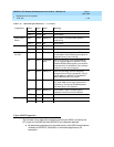
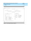
Table 1-15 shows the various LEDs on the A500 ATM switch and the meanings of
the different states.
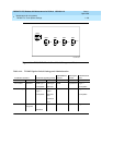
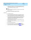
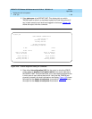
- - 100ms on /
100ms off
Loss of signal on the OC-3 fiber. Either the
TN230X-receive (top) or TN230X-transmit (bottom)
fibers are not working.
N/S Fast blink - Running DSP diagnostics or downloading code to
DSPs (typical during boot process).
- Slow blink - Board insertion has not yet completed.
- Steady on - Running maintenance tests. May appear to be blinking
if several short tests are run one after another.
Steady on - - Hardware alarm. Does not necessarily take the TN230X
out of service, for example, if one of the 24 DSPs fails
diagnostics.
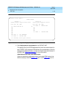
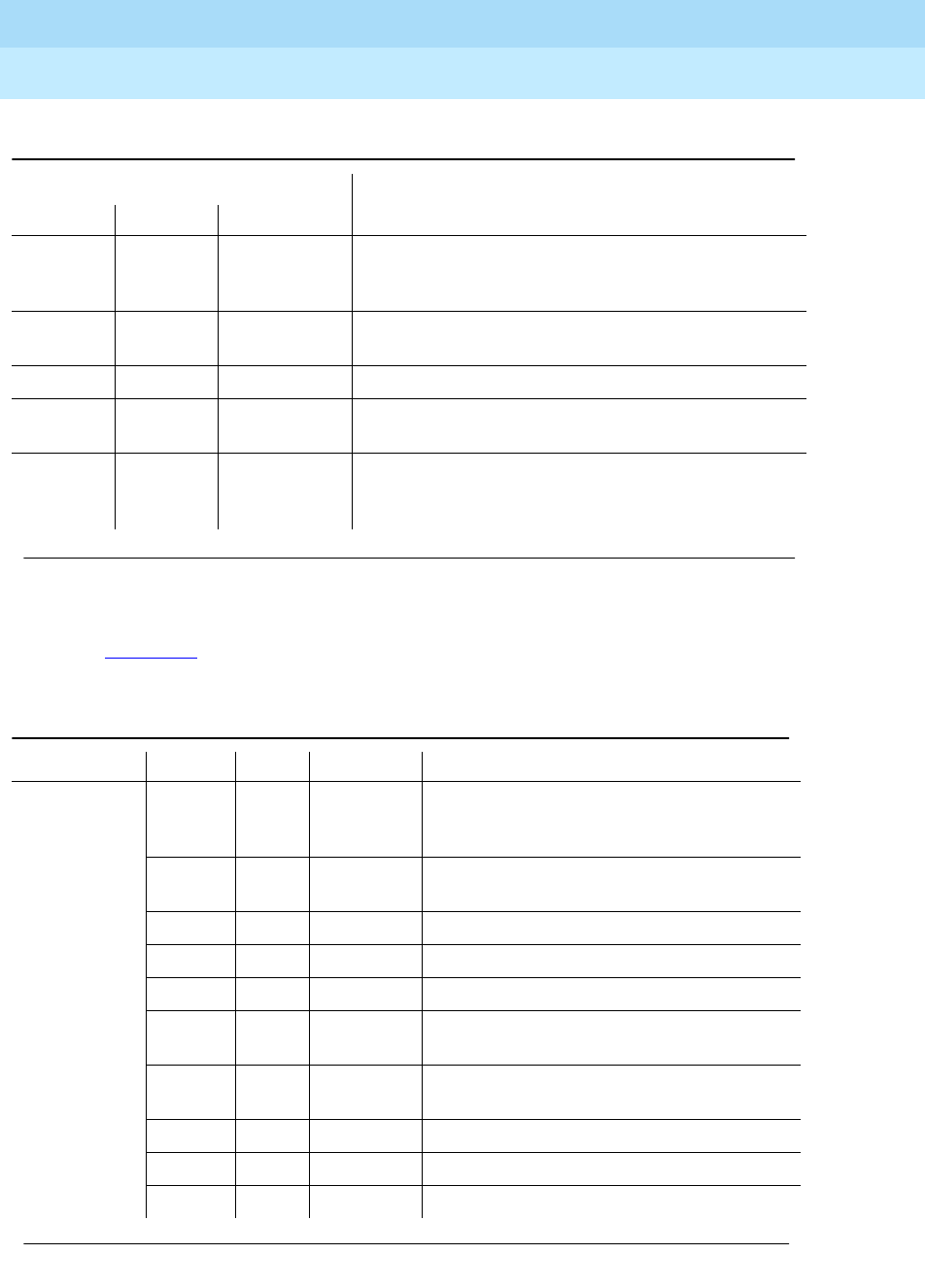
Table 1-15. A500 LED Quick Reference
Component Label Color State Meaning
Switch
Processor
Board
LK Green Intermittent
blink
Normal state. Traffic is being sent or received
over the Ethernet LAN link.
RX Green Steady on Normal state. Carrier is received over the
Ethernet LAN link.
DIAG Green Off Normal state.
NBOOT Green Off Normal state.
MGT Green Off Normal state.
RUN Green Steady on Normal state. The switch processor is
running.
PWR Green Steady on Normal state. The switch processor board is
powered up.
VOLT Yellow Off Normal state
TEMP Yellow Off Normal state
FAN Yellow Off Normal state
Continued on next page
Table 1-14. TN230X LED reference — Continued
LED color
Interpretation
Red Green Yellow
Continued on next page