


DEFINITY ECS Release 8.2 Maintenance for R8.2csi
555-233-119 Issue 1
April 2000
Maintenance Objects
3-155ATM-EI (Expansion Interface Circuit Pack)
3
19 Multiplexer
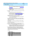
Section Remote
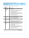
Defect Indicator:
MS_RDI
The far-end is detecting a major problem with the signal that this
board is transmitting.
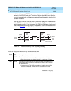
1. Make sure the ATM switch port (or a MUX port, if present
between ATM switch and the ATM-TRK board) is the same as
the ATM-TRK circuit pack’s cable interface
2. Run test board UUCSS command.
3. If Test #1259 fails with Error Code 19, connect a fiber
back-to-back in a looped mode (one strand of fiber connecting
the transmit transceiver to the receive transceiver of the board)
and see if the yellow LED flash goes away.
4. If it does the problem is off-board.
5. If the yellow LED continues to flash, replace the circuit pack; if
the error persists, escalate the problem.
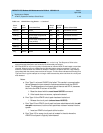
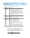
20 Loss of pointer:
LOP
ATM framer chip is unable to access the payload part of the signal.
1. Reset the board (reset board UUCSS).
2. If the error persists replace the board.
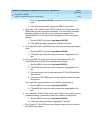
21 Path Signal Error
(PSL)
(STM1/SONET)
The incoming signal payload is not set up for transmission of ATM
data.
1. Make sure the ATM switch port (or a MUX port, if present
between ATM switch and the ATM-TRK board) is the same as
the ATM-TRK circuit pack’s cable interface.
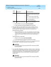
22 High-level Path
Alarm Indication
Signal:
HP_AIS
The payload is invalid.
1. Make sure the ATM switch port (or a MUX port, if present
between ATM switch and the ATM-TRK board) is the same as
the ATM-TRK circuit pack’s cable interface.
2. Run test board UUCSS.
3. If Test #1259 fails with Error Code 22, connect a fiber
back-to-back in a looped mode (one strand of fiber connecting
the transmit transceiver to the receive transceiver of the board)
and see if the yellow LED flash goes away.
4. If it does the problem is off-board.
5. If the yellow LED continues to flash, replace the circuit pack.
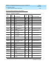
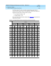
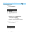
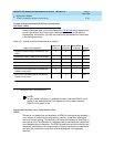
Table 3-65. Error type 1281 Aux Data and repair procedures — Continued
Aux
Data
Alarm
Description Repair procedure
Continued on next page