


DEFINITY ECS Release 8.2 Maintenance for R8.2csi
555-233-119 Issue 1
April 2000
Maintenance for csi systems
1-16Maintenance Testing
1
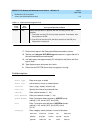
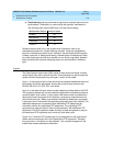
■ Fixed interval
tests are performed at regular time intervals that cannot be
administered. These tests run concurrently with periodic maintenance.
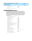
The following table lists the MOs that run fixed interval testing.
Demand tests are also run by the system when it detects a need or by
maintenance personnel in trouble-clearing activities. Using the management
terminal, maintenance personnel can “demand” the same tests that the system
initiates in periodic or background testing. Demand tests include periodic tests
plus other tests required only when trouble occurs. Some nonperiodic demand
tests are destructive (service-disrupting) tests, and are identified in boldface
type.
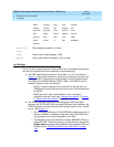
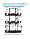
Layers
The Open System Interconnect (OSI) model for data communications contains
seven layers, each with a specific function. Communications to and through the
system concern themselves only with layers 1 and 2 of the model.
Layer 1, or the
physical layer,
covers the physical interface between devices and
the rules by which bits are passed. Among the physical layer protocols are
RS-232, RS-449, X.21, DCP, DS1, and others.
Layer 2, or the
data-link layer
, refers to code created and interpreted by the DCE.
The originating equipment can send blocks of data with the necessary codes for
synchronization, error control, or flow control. With these codes, the destination
equipment checks the physical-link reliability, corrects any transmission errors,
and maintains the link. When a transmission reaches the destination equipment,
it strips any layer-2 information the originating equipment may have inserted. The
destination equipment only passes to the destination DTE equipment the
information sent by the originating DTE equipment. The originating DTE
equipment can also add layer-2 code to be analyzed by the destination DTE
equipment. The DCE equipment treats this layer as data and passes it along to
the destination DTE equipment as it would any other binary bits.
Layers 3 to 7 (and the DTE-created layer 2) are embedded in the transmission
stream and are meaningful only at the destination DTE equipment. Therefore,
they are shown in the figure as “user-defined,” with no state changes until the
transmission stream reaches its destination.
Maintenance Object Interval (min)
POWER 60
SPE-SELEC 60
TDM-BUS 10
TONE-PT 10