


DEFINITY ECS Release 8.2 Maintenance for R8.2csi
555-233-119 Issue 1
April 2000
Maintenance for csi systems
1-104ATM Tips
1
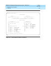
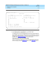
Cajun A500 Diagnostics
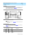
The first step in any diagnostic procedure involving the A500 is to identify the
OC-3 ports on the A500 that have DEFINITY port networks attached.
■ Be aware that customers may use other ports on the A500 for applications
unrelated to DEFINITY (LAN traffic or multimedia applications, for
examples).
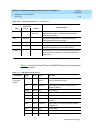
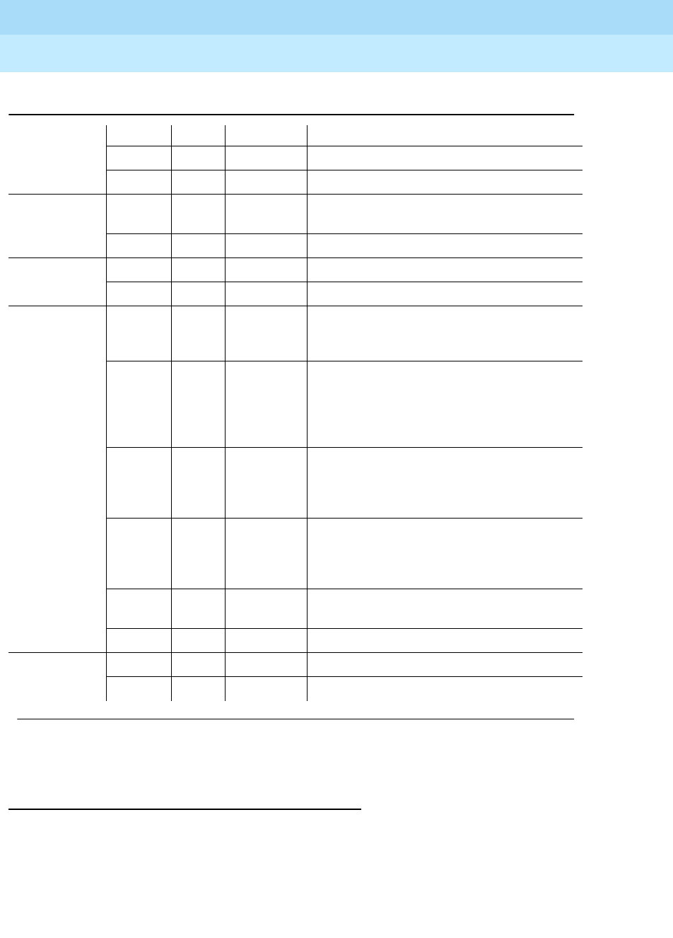
SYSERR Yellow Off Normal state
FAULT Yellow Off Normal state
Switch Fabric
Board
PWR Green Steady on Normal state. The switch fabric board is
powered up.
FAULT Yellow Off Normal state
Port Board PWR Green Steady on Normal state. The port board is powered up.
FAULT Yellow Off Normal state
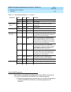
Port Board
Per Port
RX Green Off No ATM cells are being received. This is not a
normal state if the terminating port network is
supposed to be up and running.
RX Green Intermittent
blink
ATM cells are being received intermittently.
This is a typical pattern for DEFINITY if only
Variable Bit Rate (VBR) signaling connections
are present but no talk paths are up, perhaps
because no calls are in progress.
RX Green Steady on ATM cells are being received frequently
enough that the LED is lit constantly. This is a
typical pattern for DEFINITY if Constant Bit
Rate (CBR) talk paths are present.
CD Green Off Loss of carrier on the fiber. The A500 detects
only if the A500-receive (right-hand) fiber is
not working. The state of the A500-transmit
(left hand) fiber is not detected.
CD Green Steady on Normal state. There is a optical carrier
detected on the fiber from the TN230X.
RPRD Yellow Off Normal state
Power Supply AC OK Green Steady on Normal state. AC power is okay.
DC OK Green Steady on Normal state. DC power is okay.
Table 1-15. A500 LED Quick Reference — Continued
Component Label Color State Meaning
Continued on next page